Back to: PHYSICS SS1
Welcome to class!
In today’s class, we will be talking about current electricity. Enjoy the class!
Current Electricity

Current
The movement of electric charge is known as current and is measured in amperes.
Electric current is the rate of flow of charge. Potential difference is measured using a voltmeter while the current is measured using an ammeter. The SI units for a charge is amperes (A).
Potential Difference
The electric potential difference (p. d) is defined as the work done per unit charge in moving charge from one point to another. It is measured in volts.
Electromotive Force and Internal Resistance
The amount of energy supplied to a unit charge is defined as the electromotive force (or EMF). In an SI unit system, the unit of EMF is volts. A cell is said to have an EMF of 1V when it supplies 1J of energy to each 1C of charge.
Ohm’s law
This law relates the current flowing through a conductor and the voltage drop across that section of the conductor. The law states: the current flowing through a conductor is directly proportional to the potential difference across its ends provided temperature and other physical factors are kept constant. The following set up can be used to investigate Ohm’s law:
- Close the switch and adjust the current flowing through the conductor T using the rheostat to the least possible value. Record the corresponding voltmeter reading.
- Increase the current in steps recording the corresponding voltmeter readings.
- Plot a graph of voltage against the current. Hence determine the slope of the graph.
The voltage drop across the conductor is directly proportional to the current through it.
This constant is what is regarded or recorded as resistance.
V/I = constant
The constant is known as resistance R.
Thus, V/I= R
Or V= IR.
Where,
- V is the voltage in volts (V)
- R is Resistance in ohm (Ω)
- I is Current in Ampere (A)
If a substance follows Ohm’s law, then a linear relationship exists between V & I. These substances are called Ohmic substance e.g. metals and alloys. Some substances do not follow Ohm’s law, these are called a non-ohmic substance.
Diode valve, rectifier, voltage-dependent resistors, triode valve and electrolytes, are some examples of non-ohmic conductors.
The SI unit of resistance R is volt/ampere = ohm (Ω)
The inverse of resistance is called conductance;
Conductance = 1/ resistance =1/R.
Applications of Ohm’s law
The main applications of Ohm’s law are:
(1) To determine the voltage, resistance or current of an electric circuit.
(2) Ohm’s law is also used in dc ammeter and other dc shunts to divert the current.
Limitations of Ohm’s law
Following are the limitations of Ohm’s law:
(1) Ohm’s law is not applicable for unilateral electrical elements like diodes and transistors as they allow the current to flow through in one direction only.
Examples
(1) If the resistance of an electric iron is 50Ω and 3.2A Current flows through the resistance. Find the voltage between two points.
Solution
Given Parameters, Resistance (R) = 50Ω
Current (I) = 3.2A
Therefore,
Voltage (V) = I x R = 3.2A x 50 Ω =160V
(2) Calculate the current flowing through an 8Ω device when it is connected to a 12V supply.
Solution
I= V/R
I= 12V/8Ω =1.5A
(3) A current of 0.5 A is drawn by a filament of an electric bulb for 10 minutes. Find the amount of electric charge that flows through the circuit.
Solution
Given parameters;
I = 0.5A;
t = 10 min = 600s.
Q = It= 0.5 A × 600 s = 300C
Resistance
Resistance is the amount of opposition given to the flow of electric current through a conductor of electricity. It can also be defined as the ratio of voltage to current. Resistance is denoted by R, measured in ohm (Ω).
Thus, R =V/I
Therefore V = IR
Factors affecting the resistance of a conductor
- Temperature
- Length of the conductor (L)
- Cross-section area (A)
- Resistivity
Effects of the in temperature on resistance
- For Pure metal, the resistance increases.
- For Non-metals, carbon and semi-conductors, the resistance is constant.
- For alloys, the resistance is constant and so standard resistors are made of alloys such as constantan.
Measurement of resistance
Four methods may be used:
(1) Voltmeter- ammeter method:
In this method, the current flowing through the material and voltage across its ends are measured and a graph of voltage against current plotted. The slope of the graph gives the resistance offered by the material.
Difference between Voltmeter and Ammeters
In a circuit, the ammeter is always connected in series with the battery while a voltmeter is always connected parallel to the device whose voltage is being measured.
(2) The Wheatstone bridge method:
A Wheatstone bridge consists of four resistors and a galvanometer connected as shown below:
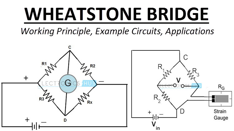
The values of three out of the four resistors must be known. The value of one of the resistors is adjusted to a point that the galvanometer does not deflect. At this point, the voltage drop across P is equal to that across Q. Similarly, the voltage drop across R is equal to that across S. Note that the current I1 flowing through P is equal that through R. Also, the current I2 through Q is the same to that through S.
Therefore, I1 P= I2Q…………………………. i
I1 R = I2S…………………………. ii
Dividing equation (i) by (ii), we get;
P/Q= R/S
This method is more accurate compared to the voltmeter- ammeter method since the voltmeter has some resistance against the flow of current and thus takes up some voltage.
(3) The metre bridge method:
This method relies on the fact that resistance is directly proportional to the length of the conductor.
I1R1= I2L2 ………………………….. iThe value of R must be known. Suppose at point K the galvanometer does not deflect, then the voltage drop across R1 equals the voltage drop across the section L1. Similarly, the voltage drop across S equals the voltage drop across the section L1. If the current through R and S is I1 and that through the section L1 and L2 is I2, then;
I1S=I2L1 …………………………… ii
Dividing equation (i) by (ii), we get;
R1/S= L2/L1
(4) Potentiometer:
Resistivity
The resistivity of a material is a fundamental property of a material that quantifies how strongly a given material opposes the flow of current. The resistivity of a material is highly dependent on temperature.
Therefore, at a constant temperature resistance varies directly as the length and inversely as the cross-section area of the conductor;
R α L/A
R= (A constant x L/A)
Or simply, AR/L= constant
The constant is called the resistivity of the material;
Resistivity = (cross section area A x resistance R) / length L.
Resistivity is measured in ohm-metre (Ωm).
Electrical conductivity
Electrical conductivity is defined as the reciprocal of resistivity. It is denoted by K and measured in Ω-1m-1 or (Ωm)-1.
Example
(1) A wire of resistance 3.5Ω has a length of 0.5m and cross-section area 8.2 x 10⁻⁸m2. Determine its resistivity.
Solution
Resistivity = AR/L = (8.2 x 10⁻⁸m2 x 3.5Ω)/0.5m
= 5.74 x 10⁻⁷Ωm
In our next class, we will be talking about Resistors. We hope you enjoyed the class.
Should you have any further question, feel free to ask in the comment section below and trust us to respond as soon as possible.