Back to: PHYSICS SS1
Welcome to class!
In today’s class, we will be talking about resistors. Enjoy the class!
Resistors

Resistors in series and parallel combinations
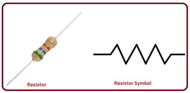
A resistor is a passive two-terminal electrical component that implements electrical resistance as a circuit element. Resistors reduce the current flow and lower voltage levels within circuits. It also means a specially designed conductor that offers particular resistance to the flow of electric current. Most circuits often have more than one resistor to limit the flow of charges in a circuit. The two simplest combinations of resistors are – series and parallel. Also, there are three main groups of resistors:
(1) Fixed resistors: offer fixed values of resistance. They have colour bands around them.

(2) Variable resistors: offer varying resistance e.g rheostat and potentiometer.
(3) Non-linear resistors: the current flowing through these resistors does not change linearly with the voltage applied. Examples include a thermistor and light-dependent resistor
Circuit
A circuit is composed of conductors (wire), power source, load, resistor, and switch. A circuit starts and ends at the same point. Usually, copper wire without insulation is used as a conductor. A switch is used to make or break a circuit. Resistors control the flow of the electric current in a circuit. A resistor is a passive element which means that it only consumes power but does not generate power. A load in a circuit consumes electrical energy and converts it into other forms of energy like light, heat, etc. A load can be a light bulb, fan, etc.
Why do we need a combination circuit?
In an electric circuit, the different components are connected either in series or in parallel to produce different resistive networks. Sometimes, in the same circuit, resistors can be connected in both parallel and series, across different loops to produce a more complex resistive network. These circuits are known as mixed resistor circuits. In the end, however, the total resistance should be known. It is important to know how to do this because resistors never exist in isolation. They are always part of a larger circuit that will have many resistors connected in different combinations. So how do we calculate this total resistance for resistors in series and parallel circuits? In the next section, let us look at how the total resistance is calculated in a circuit with different resistor combinations.
Resistors in series
A circuit is said to be connected in series when the same amount of current flows through the resistors. In such circuits, the voltage across each resistor is different. In a series connection, if any resistor is broken or a fault occurs, then the entire circuit is turned off. The construction of a series circuit is simpler compared to a parallel circuit.
From Ohm’s law, V= IR.
The voltage drop across R1; V1= IR1
The voltage drop across R2; V2 =IR2
The voltage drop across R3; V3=IR3
And the total circuit voltage V= V1+V2+V3.
Thus V= IR1+IR2+IR3=I(R1+R2+R3)
V/I =(R1+R2+R3)
But V/I = R
Thus the combined circuit resistance R=R1+R2+R3.
Generally, the effective resistance of resistors arranged in series is equal to the sum of the individual resistances.
Resistors in parallel
A circuit is said to be connected in parallel when the voltage is same across the resistors. In such circuits, the current is branched out and recombines when branches meet at a common point. A resistor or any other component can be connected or disconnected easily without affecting other elements in a parallel circuit.
Suppose the current flowing through R1 is I1, through R2 is I2 and through R3 is I3 then:
The voltage drop across R1; V1=I1R1
The voltage drop across R2; V2=I2R2
The voltage drop across R3; V3=I3R3
But V1= V2= V3= V and I=I1+I2+I3
Therefore, I=V/R1 + V/R2 + V/R3
I/V = (1/R1 + 1/R2 + 1/R3)
But I/V= 1/R.
Hence 1/R= 1/R1 + 1/R2 + 1/R3
R is the combined circuit resistance.
For the problem given above, what if the resistors were connected in parallel instead of in series? What is the total resistance in that case?
A special case of two resistors in parallel
It follows that 1/R= 1/R1+1/R2
1/R= (R1+R2)/R1R2
Hence the effective resistance R= R1R2/ (R1+R2).
Generally, for n resistors arranged in parallel, the effective resistance of the arrangement is given by; 1/R=1/R1+1/R2+…………..+1/Rn
Note: When a circuit comprises of both series and parallel connections, the arrangement is systematically reduced to a single resistor.
Electromotive force and internal resistance of a cell
An emf (electromotive force) device has a positive terminal (at high potential) and a negative terminal (at low potential). This device is responsible for moving a positive charge within itself from the negative terminal to the positive terminal.
For this to happen, work is done by some agency in the emf device. The energy required to do this work is chemical energy (as in a battery), mechanical energy (as in an electric generator), temperature difference (as in a thermopile).
The emf is thus given by the formula
The S.I unit of emf is (V)
Note:
- Electromotive force is not a force but a potential difference.
- E.m.f. can be defined as the work done in moving a charge once around a closed circuit.
INTERNAL RESISTANCE (r)
The potential difference across a real source of emf is not equal to its emf. The reason is that the charge which is moving inside the emf device also suffers resistance. This resistance is called internal resistance of the emf device.
E = IR + Ir = V + Ir
⇒ V = E – Ir
Note:
- Emf is the property of a cell but terminal potential difference depends on the current drawn from the cell.
Short-circuiting
When the terminals of an emf device are connected with a conducting path without any external resistance then
E = Ir ⇒
Since internal resistance has a very small value, therefore a very high current flows in the circuit producing a large amount of heat. This condition is called short-circuiting.
During short-circuiting, the terminal potential difference is zero.
Combination of cells
Series combination of cells:
Equivalent Emf
EAB = E1 + E2 + … + En
Equivalent internal resistance,
RAB = r1 + r2 + ……. + rn
Parallel combination of cells:
Equivalent emf
Equivalent internal resistance
Worked examples
(1) A resistor having an electrical resistance value of 100 Ω is connected to another resistor with a resistance value of 200 Ω. The two resistances are connected in series. What is the total resistance across the system?
Solution
Here, R1 = 100 Ω and R2= 200 Ω
Rtotal = 100 + 200 = 300 Ω
(2) Three resistors each of resistance 5 Ω are arranged in series in a circuit. What is the equivalent resistance of the circuit?
Solution
RT = R1 + R2 + R3 + R4 + R5
RT = 5 + 5 + 5 = 15 Ω
(3) Three resistors of resistance 1 Ω, 2 Ω and 4 Ω are connected in series. Find the equivalent resistance of the combination.
Solution
RT = R1 + R2 + R3
RT = 1 + 2 + 4 = 7
In our next class, we will be talking about Electrical Energy and Power. We hope you enjoyed the class.
Should you have any further question, feel free to ask in the comment section below and trust us to respond as soon as possible.

This really helpful
Very helpful
Thanks alot
Very good
Thank you
This was very helpful
Good but further example
We need more exampld