Back to: Basic Technology JSS 1
Welcome to class!
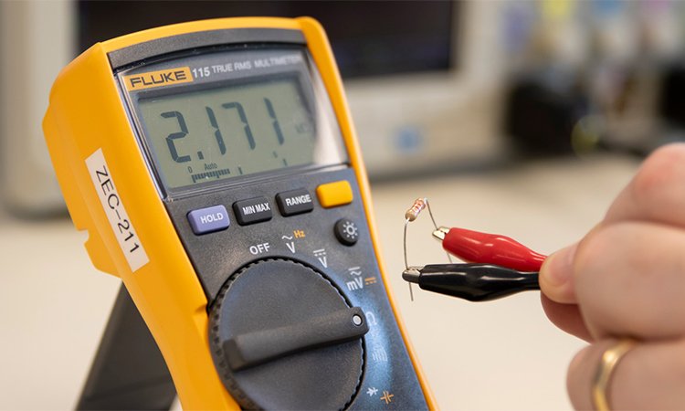
In today’s class, we will be talking more about electricity. Enjoy the class!
Measuring Instruments: Definition of Transformer, Stabilizer, Electrical Appliances and Accessories
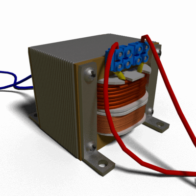
Transformer
A transformer is a static device which transfers electrical energy from one circuit to another through the process of electromagnetic induction. It is most commonly used to increase (‘step up’) or decrease (‘step down’) voltage levels between circuits.
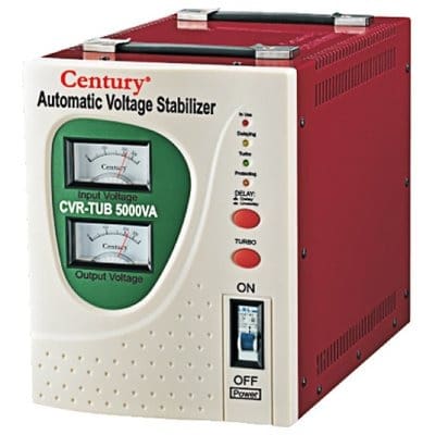
Stabilizer
A device that automatically maintains a constant voltage at the inputs of any receiver of electric power (voltage stabilizer) or a constant current in the circuits of such receivers (current regulator). Constant values are maintained regardless of variations in the mains voltage or load.
Working principle of transformer
The working principle of a transformer is very simple. Mutual induction between two or more winding (also known as coils) allows for electrical energy to be transferred between circuits. This principle is explained in further detail below.
The three main parts of a transformer:
- Primary Winding of Transformer
- Magnetic Core of Transformer
- Secondary Winding of Transformer
- The primary winding of transformer:
It produces magnetic flux when it is connected to an electrical source.
- The magnetic core of the transformer:
The magnetic flux produced by the primary winding, that will pass through this low reluctance path linked with secondary winding and create a closed magnetic circuit.
- The secondary winding of transformer:
The flux, produced by primary winding, passes through the core, will link with the secondary winding. This winding also wounds on the same core and gives the desired output of the transformer.
Types
1. Coil rotation AC voltage regulators:
It is an older type of voltage regulator which was used in the 1920s. It works on the principle similar to the variocoupler and consists of two field coils: one coil is fixed and the other can be rotated on an axis which is parallel with the fixed coil.
2. Electromechanical Regulators:
Electromechanical voltage regulators that are used for regulating the voltage on AC power distribution lines also called as voltage stabilizers or tap-changers. To select an appropriate tap from multiple taps of an autotransformer, these voltage stabilizers utilize the servomechanism operation.
3. Constant Voltage Transformer:
It is a type of saturating transformer which is used as a voltage stabilizer; it is also called as Ferro resonant transformer or Ferro resonant regulator. These voltage stabilizers use a tank circuit composed of a capacitor for generating nearly constant average output voltage with varying input current and a high-voltage resonant winding. By the magnetic saturation, the section around secondary is used for regulating the voltage.
In our next class, we will be talking more about Basic Electricity. We hope you enjoyed the class.
Should you have any further question, feel free to ask in the comment section below and trust us to respond as soon as possible.