Back to: Basic Technology JSS 1
Welcome to class!
In today’s class, we will be talking about simple electricity circulation. Enjoy the class!
Simple Electrical Circulation

A circuit is a closed path that electrons flow along to provide power to your home and electronics. A simple electric circuit contains a power source (battery), wires, and a resistor (light bulb)
Building an electrical circulation with a battery
- Gather the necessary materials. To build a simple circuit, you will need a power source, 2 insulated wires, a light bulb, and a light bulb holder. A power source can be any type of battery or battery pack. The rest of the materials can be found at your local hardware store.
- Strip the ends of the insulated wires. For your circuit to work properly, the wires need to be exposed so you must strip the ends. Using wire strippers, remove about 1 inch (2.5 cm) of the insulation from the ends of each wire.
- Install batteries into the battery pack. Depending on the type of batteries you are using, you may be able to skip this step. If you are using multiple batteries, you will need a power pack to hold the batteries. Push each battery in by the side taking care to put the positive and negative ends in the correct orientation.
- Attach your wires to the battery pack. The wires will be conducting your electric current from the batteries to the light bulb. The easiest way to attach the wires is to use electrical tape. Attach the end of one wire to one side of the battery, making sure that the wire maintains contact with the metal of the battery. Repeat with the other wire on the other side of the battery.
- Fasten the other end of the wire to the metal screw of the bulb holder. Take the exposed metal end of each wire and bend it into a U-shape. Loosen each screw on the light bulb holder just enough to slip the U-shape of the wire around the screw. Each wire will be attached to its screw. Tighten the screw, ensuring that the metal of the wires remains in contact with the screw.
- Test your circuit. Screw the light bulb into its holder until it is tight. If your circuit is hooked up properly, the bulb should light up when fully screwed into its socket.
Simple Electrical Connections- Simple Electrical Circuit Diagram
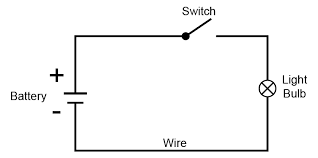
An electrical connection is an electrical installation of cabling and associated devices such as switches, distribution boards, sockets, and light fittings in a structure. It is also called electrical wiring.
Wiring is subject to safety standards for design and installation. Allowable wire and cable types and sizes are specified according to the circuit operating voltage and electric current capability,
A circuit diagram is a visual display of an electrical circuit using either basic images of parts or industry-standard symbols. These two different types of circuit diagrams are called pictorial (using basic images) or schematic style (using industry-standard symbols)
-
DC lighting circuit:
For a small LED lamp, normally we use a DC supply (battery). This circuit is very simple. The battery has two points, anode and cathode. The anode is positive and the cathode is negative. A lamp has two terminals – one is positive and the other is negative. The positive terminal of the lamp is connected to the anode and the negative terminal of the lamp is connected to the cathode of the battery. Once the connection is made the lamp will glow.
-
Switch circuit:
We operate switches for lights, fans etc. Many times a day but we usually don’t try to see the connection made inside the switch. The function of the switch is to connect or complete the circuit going to the load from the supply. It has moving contacts which are normally open.
-
AC Circuit for Lamp:
For a lamp we need two wires; one is the neutral wire and the other is the live wire. These two wires are connected from the lamp to the main supply panel. It is advisable to use different colours for live wires and neutral wires. The universal practice is to use the colour red for live wires and black colour for the neutral wire.
-
Battery Charging Circuit:
Battery charging is done by means of a rectifier. The main function of the rectifier is to convert AC (alternating current) into DC (direct current). The rectifier shown in the diagram is the bridge rectifier, which has four diodes connected in the form of a bridge.
We hope you enjoyed the class.
Should you have any further question, feel free to ask in the comment section below and trust us to respond as soon as possible.