Back to: PHYSICS SS3
Welcome to class!
In today’s class, we will be talking about electromagnetic induction. Enjoy the class!
Electromagnetic Induction

Electromagnetism is the effect resulting from the interaction between an electric current and a magnetic field. This effect brings about induced electromagnetic force (e.m.f) and the resulting current is called induced current.
Experiments on electromagnetic induction
Consider the following diagram
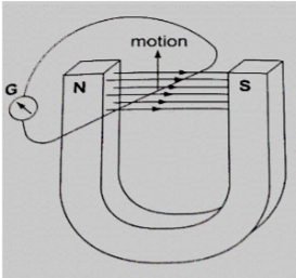
When the wire is moved up the galvanometer deflects in one direction then the opposite direction when moved downwards.
When moved horizontally or held in a fixed position there is no deflection in the galvanometer.
This shows that e.m.f is induced due to the relative motion of the wire or the magnet.
Factors affecting the magnitude of the induced e.m.f
- The rate of relative motion between the conductor and the field: if the velocity of the conductor is increased the deflection in the conductor increases.
- The strength of the magnetic field: a stronger magnetic field creates a bigger deflection
- The length of the conductor: if the length is increased in the magnetic field the deflection increases.
Faraday’s law of magnetic induction
After considering the factors affecting the magnitude of the induced e.m.f, Michael Faraday came up with a law which states that “The induced e.m.f in a conductor in a magnetic field is proportional to the rate of change of the magnetic flux linking the conductor”.
Lenz’s law of electromagnetic induction
This law is used to determine the direction of the induced current in a conductor. It states that “An induced current flows in such a direction that its magnetic effect opposes the change through which the current has been produced”.
It is applied similarly when a wire is been moved in the magnetic field.
Fleming’s right-hand rule
The law states that “The first finger, the second finger and the thumb of the right hand when placed mutually perpendicular to each other, the first finger points in the direction of the field and the thumb in the direction of motion then second finger points in the direction of the induced current”. This law is also called the generator rule.
Applications of electromagnetic induction
- A.c generator/alternator: a generator is a device which produces electricity based on electromagnetic induction by continuous motion of either a solenoid or a magnet. It consists of an armature made of several turns of insulated wire wound on soft iron core and revolving freely on an axis between the poles of a powerful magnet.
Two slip rings are connected to the ends of the armature with two carbon brushes rotating on the slip ring.
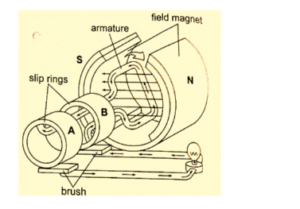
In an external circuit, the current is at a maximum value at 900 and minimum value at2700.
This brings about alternating current and the corresponding voltage (e.m.f) is the alternating voltage. They are used in car alternators and H.E.P.
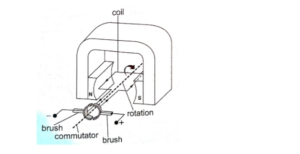
- D.c generator/alternator: in this case, the commutators replace the slip rings to enable the output to move in one direction.
- Moving coil microphone: it consists of a coil wound on cylindrical cardboard which opens into a diaphragm. The coil is placed between the poles of a magnet as shown.
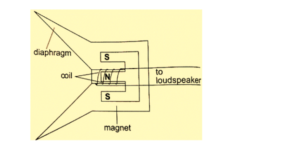
As sound waves hit the diaphragm, they vibrate and move the coil which produces induced current into the coil and then it flows to the loudspeakers.
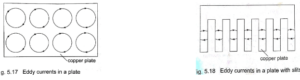
Eddy currents
They are composed of loops of current which have a magnetic effect opposing the force-producing them.
When a copper plate with slits is used the loops are cut off and hence the effective currents are drastically reduced and so is the opposing force.
Practically eddy currents are reduced by laminating metal plates. Armatures of electric generators and motors are wound on laminated soft iron cores.
The lamination slices, which are quite thin are glued together by a non-conducting glue and this reduces eddy currents to an almost negligible value.
Eddy currents are useful in moving coil meters to damp the oscillations of the armature when the current is switched off.
Mutual induction
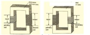
Mutual induction is produced when two coils are placed close to each other and a changing current is passed through one of them which in turn produces an induced e.m.f in the second coil. Therefore mutual induction occurs when a changing magnetic flux in one coil links to another coil.
Applications of mutual induction
1. The transformer: it converts an alternating voltage across one coil to a larger or smaller alternating voltage across the other. Since H.E.P is lost through transmission lines therefore it is stepped down before it is transmitted and stepped up again at the point of supply lines.
In a step-up transformer, the number of turns in the secondary coil (Ns) is higher than the number of turns in the primary coil (Np).
In a step-down transformer, the primary coil has more turns than the secondary coil.
The relationship between the primary voltage and the secondary voltage is given by;
Np / Ns = Vp / Vs.The efficiency of a transformer is the ratio of power in the secondary coil (Ps) to power in primary coil (Pp), therefore efficiency = Ps / Pp × 100%.
Worked examples
(1) A current of 0.6 A is passed through a step-up transformer with a primary coil of 200 turns and a current of 0.1 A is obtained in the secondary coil. Determine the number of turns in the secondary coil and the voltage across if the primary coil is connected to a 240 V mains.
Solution
Np / Ns = Vp / Vs = Ip / Is = Ns = (0.6 × 200) / 0.1 = 1200 turns
Vp = 240 V hence Vs = (240 × 1200) / 200 = 1440 V
(2) A step-up transformer has 10,000 turns in the secondary coil and 100 turns in the primary coil.
An alternating current of 0.5 A flows in the primary circuit when connected to a 12.0 V a.c. supply.
- a) Calculate the voltage across the secondary coil
- b) If the transformer has an efficiency of 90%, what is the current in the secondary coil?
Solution
- a) Vs = (Ns / Np) × Vp = (10,000 × 12) / 100 = 1200 V
- b) Power in primary = Pp = Ip × Vp= 5.0 × 12 = 60 W
Efficiency = Ps / Pp × 100% but Ps = Is Vs
Is = (60 × 90) / (1200 × 100) = 0.045 A
Energy losses in a transformer
Loss of energy in a transformer is caused by;
- Flux leakage: this may be due to poor transformer design
- Resistance in the windings: it is reduced by using copper wires which have very low resistance
- Hysteresis losses: caused by the reluctance of the domains to rotate as the magnetic field changes polarity. Reduced by using materials that magnetize and demagnetize easily like soft iron in the core of the transformer.
- Eddy currents: reduced by using a core made of thin, well insulated and laminated sections.
Uses of transformers
- Power stations: used to step up or down to curb power losses during transmission
- Supplying low voltages for school laboratories
- Low voltage supply in electronic goods like radios, TVs etc.
- High voltage supply in cathode ray oscilloscope (CRO) for school laboratories.
- Induction coil: was developed in 1851 by Heinrich Ruhmkortt. It has both secondary and primary coils with an adjustable spark gap.
- Car ignition system: it is applied in petrol-driven engines where a spark plug is used to ignite petrol vapour and air mixture to run the engine.
Presentation
- Introduce the lesson by giving them definitions of Electromagnetic induction.
- Explain all the definitions by giving examples on each of them.
- Pick out the keywords in the definitions and explain to them.
- Ask them to defined Faraday’s Law on Induction by using their own words and correct them if necessary.
- States the uses of a transformer
- Solve questions on transformer.
Closure/summary
Teacher summarizes the lesson.
General evaluation
- State the laws of electromagnetic induction
Assignment
1. A transformer is used to light a lamp rated at 250V, 100W from a 25V a.c. main supply. Calculate the:
(i) Efficiency of the transformer if the current in the primary circuit is 5A
(ii) Peak value of the output voltage.
In our next class, we will be talking about Electric Field. We hope you enjoyed the class.
Should you have any further question, feel free to ask in the comment section below and trust us to respond as soon as possible.