Back to: PHYSICS SS3
Welcome to class!
In today’s class, we will be talking about electromagnetic induction. Enjoy the class!
Electromagnetic Induction

Electromagnetic induction is the production of electric current or voltage in a conductor whenever there is a relative motion between the conductor and a magnetic field (or a magnet)
Induced E.M.F in a straight conductor, Fleming’s right-hand rule
An induced E.M.F is produced in a straight conductor when the conductor moves across the lines of force of a uniform magnetic field. The direction of the induced E.M.F is given by Fleming’s Right Hand Rule.
It states that if the thumb, forefinger and the middle finger of the left hand are held mutually at right angles to each other, with the forefinger pointing in the direction of the field and the thumb pointing in the direction of motion, then the middle finger will point to the induced e.m.f. or current, I.
Mathematically,
E.m.f = Blv
Volt = Weber(m) x m x m/s
Laws of electromagnetic induction
There are two laws of Electromagnetic Induction:
- Faraday’s Law and
- Lenz’s law
Faraday’s law
The result of the Faraday’s experiment is summed up in the law of electromagnetic induction which states that whenever there is a change in the magnetic flux linked with a circuit, an electromotive force is induced. This strength e.m.f. is proportional to the rate of charge of the flux linked with the circuit.
Lenz’s law
Another law of electromagnetic induction is Lenz’s law. Henry Lenz’s made observation of the direction of the induced current and summed it up in his law, which states that “The direction of the induced current is always such as to oppose the charge (motion) producing it.
This is often called Faraday’s second law of electromagnetic induction.
The factors on which the magnitude of the induced e.m.f depends on are as follows:
- The strength of the magnet
- Numbers of turns of the solenoid (Coil)
- The surface area of the coil
- The distance between the magnet and the coil
When a metallic sheet, either in a moving magnetic field or in a changing magnetic field occurs, an induced current flows. This current is called the Eddy Current.
The effect can be reduced by increasing the resistance of the eddy current path and by
- laminating the core
- using a bundle of iron wires
- using a pack of iron dust
Application of electromagnetic induction
Application of electromagnetic induction can be seen in the following:
- Induced Coil
- Dynamo or generator
- Transformers
Induced coil
This is an electric device that is capable of producing a very high intermittent e.m.f. by electromagnetic induction from a low voltage d.c. source e.g. a battery.
Structure
It consists of
- Primary coil
- Secondary Coil.
- Make and break down device consisting of a soft iron armature.
When the key is held down firmly and the current is flowing steadily in the primary coil, the galvanometer shows no deflection. A current flows in the secondary coil only when there is a current change in the primary coil. The changing current in the primary coil produces a changing magnetic field, which in turn induces a current in the secondary coil.
Uses of the induction coil
- In radio transmission
- Application to the coil ignition system of motor vehicles
- Operating X-ray tubes.
Generator
A Generator is a device the produces current when current moves across magnetic field lines. There are two classes of generators; D.C generator (Direct Current) and A.C Generator (dynamo)
D.C generator
This generator produces a current that always has a particular direction of flow. It is obtained by using a split ring commutator.
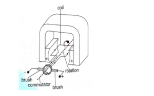
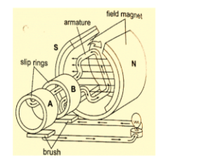
- C. Generator (Dynamo)
The working principle goes thus:
When a coil, with one turn, rotates on a shaft between the poles North-South of a magnet (horseshoe). The coil ends are connected to slip ring which is supported by the shaft by dishes of insulating materials. Carbon brushes are used to support the slip ring and connected to a lamp.
E.m.f of a generator
E = E0 sin
Where E0 = NAB
E = NAB sin
When = 90°
Therefore:
E = NAB
Note also that = 2πf
= 2πft
E = E0 sin 2πft
Transformer
Transformers are essential devices in the electrical system. It is a device for stepping up or stepping down an alternating voltage. The change on alternating voltage from a smaller to a high value (Step-up transformer) of from a higher to a lower value (Step-down transformer)
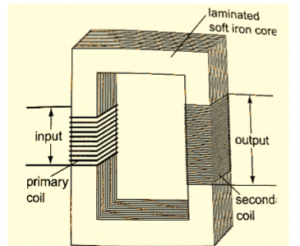
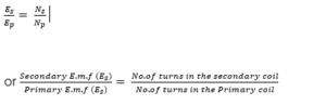
In a transformer, there are two coils the primary and the secondary coils. In a step-up transformer, there are more turns in the Ns > Np. The output voltage at the secondary coil is greater than the input voltage applied at the primary coil; i.e. Vs > Vp. On the other hand in the secondary coil. i.e. Np > Ns and Vp > Vs
Np= number of turns in the primary
Ns = number of turn in secondary
Vp = voltage applied to the primary coil
Vs = voltage applied to the secondary coil
Mutual inductance
It is the flow of induced current or voltage in a coil due to an alternating or varying current in a neighbouring coil.
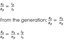
The formula for calculating the transformer
in an ideal transformer, with a 100% efficiency, the power developed in the secondary coil is equal to the power developed in the primary coil. This follows the law of conversation of energy.
Thus:
Is x Es = Ip x Es
Where Is, Ip are the secondary and primary currents. Hence
The efficiency of a transformer
![]()
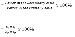
Hence, output power = Es x Is
Input Power = Ep x Ip
Losses in a transformer
Energy losses are due to
(i) Copper losses: this is the energy loss in form of heat (I2R) in the coils.
Reduction:
This is reduced by making the coil wire flow low resistance, i.e. insulating the wire
(ii) Eddy current: Energy is a loss in form of eddy current formed in the soft iron core.
Reduction:
This is reduced by laminating the core to reduce losses due to eddy current, i.e. (unwanted induced currents)
(iii) Hysteretic losses: These are as a result of the reversal in magnetism changing polarity in step with induced voltage.
Reduction:
This is reduced by designing an efficient core and using special alloys in the coil of the primary coil.
(iv) Flux leakage: Energy is lost due to leakage of magnetic flux or force, for a poorly designed core.
Reduction:
This is reduced by limiting the air gap in the core.
Worked examples
(1) A transformer has 500 turns in the primary coil and 300 turns in the secondary coil. If the primary coil is connected to a 220V mains. What voltage will be obtained from the secondary coil? What type of transformer is this?
Solution
Given Parameters;
Ep = 220V
Es = Unknown
Ns = 300 turns
Np = 500 truns
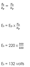
It is a step-down transformer because the secondary voltage is less than the primary voltage (132 220) and also turns is less than 1
(2) Find the value of E in the information given below:
Frequency = 60Hz
Time = 0.25 secs
E0 = 233V
Using the equation, E = E0 sin 2πf
Solution
E = 233 x sin (2 x 3.142 x 60)
E = 232.35V
General evaluation
- Define Electromagnetic Induction
Assignment
- If a transformer is used to light lamp rated at 60 W, 220V from a 440V a.c. supply, calculate
- The ratio of the number of turns of the primary coil to the secondary coil in the transformer.
- Current taken from the mains circuit if the efficiency of the transformer is 95%.
In our next class, we will be talking about Gravitational Field and Law. We hope you enjoyed the class.
Should you have any further question, feel free to ask in the comment section below and trust us to respond as soon as possible.