Back to: PHYSICS SS3
Welcome to class!
In today’s class, we will be talking more about the alternating current circuit. Enjoy the class!
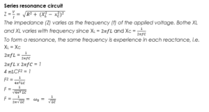
Alternating Current Circuit II
Reactance
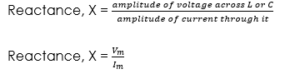
The opposition offered by the passage of an alternating current by either the induction or the capacitor or both is called reactance. It is denoted by X, measured in ohms (Ω).
Thus, the reactance X of an inductor L, or capacitor, C can be defined by the equation:
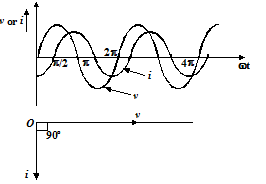
A.C. circuit containing inductor only (Inductive circuit)
Inductance is a property of the circuit which opposes a change of current, In an A.C circuit, current and voltage are continually changing the effect of the inductance to cause a continuous opposition to the change in current.
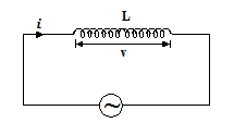
As a result of this opposition, the circuit changes are delayed in relation to the voltage changes during the circuit.
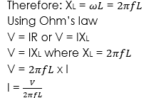
Inductive reactance
This is defined as the opposition given to the flow of current in a.c. circuit through an inductor. It is denoted by XL and measured in Ohm (Ω).
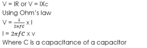
Capacitive reactance
This is defined as the opposition given to the flow of current in an a.c. circuit through a capacitor. It is denoted by XC and measured in Ohm (Ω).
The reactance for a capacitor is given by ![]()
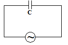
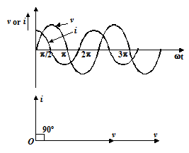
A.C. circuit containing capacitance only (Capacitive circuit)
Resistance and inductance in series A.C. circuit
In a circuit containing a pure inductance L and a pure resistance R connected in series as shown in the figure, when an A. C. voltage is applied in this circuit, the voltage drops on the resistance say vR(= iR in phase with current) and on the L say vL (= ωL), leading the current by 90o. These voltages are shown by the
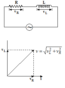
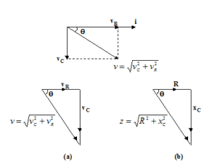
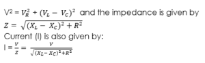
vector diagram in figure. The resultant voltage is given by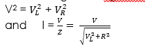
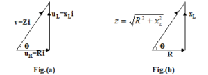
The term is called impedance of the circuit and denoted by Z (its units are ohm) i.e. ![]()
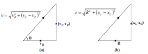
The triangle whose sides are proportional to the voltages are called voltage triangle (fig. (a)) and a triangle whose sides are proportional to R, XL and Z is called impedance triangle (fig. (b)).
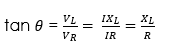
Average power in R and L in series circuit when A. C. current passes is given by
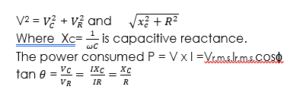
P=Vr.m.s.Ir.m.s.cosϕ
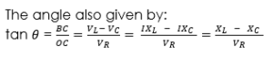
where ϕ is the angle by which vector v leads the vector i. The value of cos ϕ (=R/Z) is constant for a given circuit and is known as the power factor. It is defined as the factor by which product of RMS current and voltage should be multiplied to have true power in watt.
If ϕ is 90o i.e. cos ϕ = 0, the ohmic resistance of the A. C. current is zero and the average power also remains zero, i.e. despite the flow of current there is no dissipation of energy. The current in such a circuit is called wattles current. In practice, we cannot have a resistance-free circuit and hence wattles current is not a reality.
Resistance and capacitance in series A.C. circuit
Such a circuit having resistance, capacitance in series with an A. C. source is
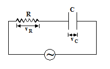
The voltage and current vectors are as shown in the figure. The voltage and impedance triangles are shown in the figure are given as
RLC series A.C. circuit
A circuit having resistance R, inductance L and capacitance C in series with an
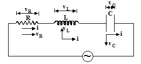
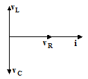
- C. source is shown in the figure. The voltage drop across resistance R be VRin phase with current, the voltage drop across inductance L be VLleading the current by 90o and voltage drop across capacitance C be vc lagging the current by 90o. The resultant of vL and vC, (vL – vC) leads the current by 90o, provided (vL > vC) and will lag current by 90o if vC > vL. The resultant voltage is given by
The voltage triangle and impedance triangle are shown in figure
Impedance
The overall opposition of a mixed circuit to the flow of an alternating current in a resistor and or a capacitor is known as impedance.
Impedance 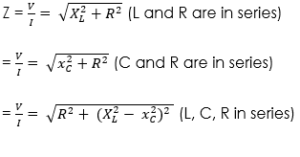
Worked examples
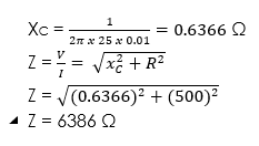
(1) A series circuit consists of a capacitor of 1 and a resistor of 500 Ω. An a.c. voltage of 6 Volts (r.m.s) and frequency 25Hz is applied. Calculate the f
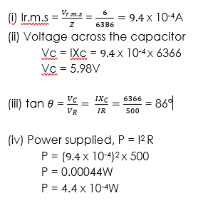
(i) Current flowing
(ii) Voltage across the capacitor
(iii) Phase angle between current and voltage
(iv) Average power
Solution
Given parameters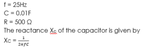
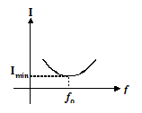
At resonance, the impedance of the circuit is maximum according to the following graph

At resonance, the current flowing through the circuit will be minimum
Application of resonance
- It is applied in the broadcasting industry
- It is also used in some sound instrument.
- Resonance makes transmission and reception of radio waves possible.
General evaluation
- A circuit consists of a capacitor of 2 and a resistor of 1000 ohms. An alternating e.m.f. of 12V and frequency 50Hz is applied. calculate the:
- Current flowing
- The voltage across the capacitor
- The phase angle between the applied e.m.f. and current
- The average power supplied.
In our next class, we will be talking about Atomic Models. We hope you enjoyed the class.
Should you have any further question, feel free to ask in the comment section below and trust us to respond as soon as possible.