Back to: COMPUTER SCIENCE JSS3
Welcome to Class !!
We are eager to have you join us !!
In today’s Computer Science class, We will be discussing Logic Circuit. We hope you enjoy the class!
LOGIC CIRCUIT
A logic gate is an elementary building block of a digital circuit. Most logic gates have two inputs and one output. At any given moment, every terminal is in one of the two binary conditions low (0) or high (1), represented by different voltage levels. The logic state of a terminal can, and generally does, change often, as the circuit processes data. In most logic gates, the low state is approximately zero volts (0 V), while the high state is approximately five volts positive (+5 V).
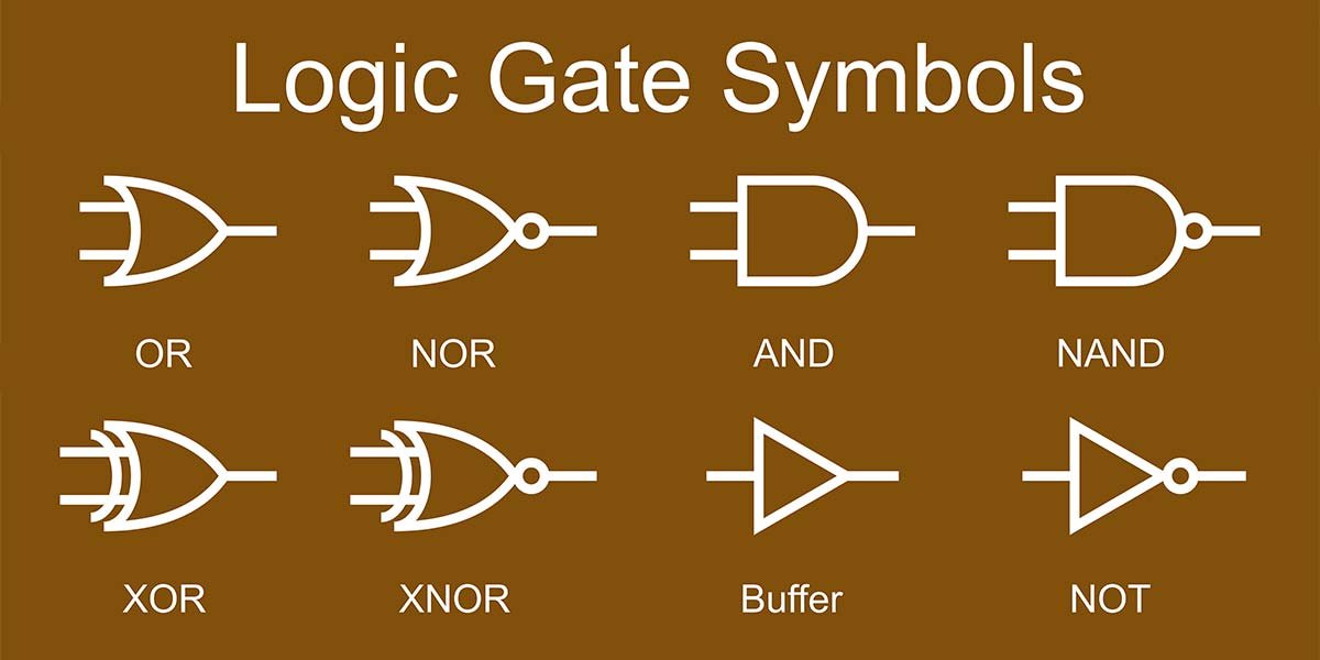
There are seven basic logic gates: AND, OR, XOR, NOT, NAND, NOR, and XNOR.
AND GATE
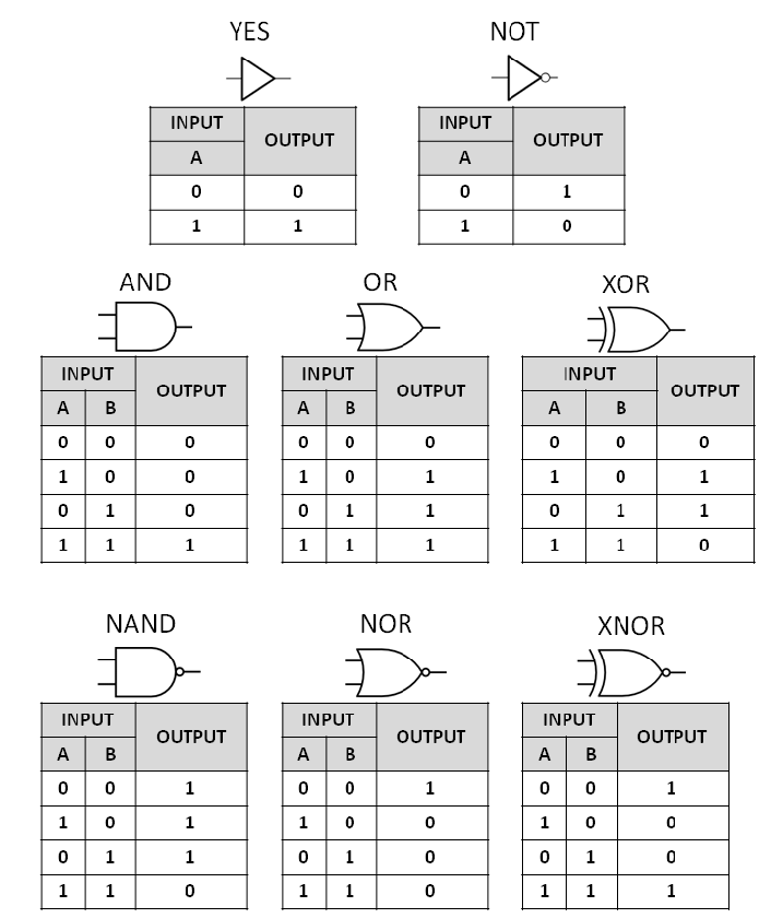
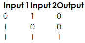
The AND gate is so named because, if 0 is called “false” and 1 is called “true,” the gate acts in the same way as the logical “and” operator. The following illustration and table show the circuit symbol and logic combinations for an AND gate. (In the symbol, the input terminals are at left and the output terminal is at right.) The output is “true” when both inputs are “true.” Otherwise, the output is “false.”
OR GATE
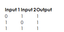
The OR gate gets its name from the fact that it behaves after the fashion of the logical inclusive “or.” The output is “true” if either or both of the inputs are “true.” If both inputs are “false,” then the output is “false.”
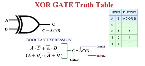
XOR GATE
The XOR (exclusive-OR ) gate acts in the same way as the logical “either/or.” The output is “true” if either, but not both, of the inputs, are “true.” The output is “false” if both inputs are “false” or if both inputs are “true.” Another way of looking at this circuit is to observe that the output is 1 if the inputs are different, but 0 if the inputs are the same.
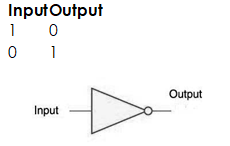
Inverter or NOT gate
A logical inverter, sometimes called a NOT gate to differentiate it from other types of electronic inverter devices, has only one input. It reverses the logic state.
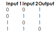
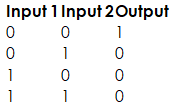
NAND GATE
The NAND gate operates as an AND gate followed by a NOT gate. It acts in the manner of the logical operation “and” followed by negation. The output is “false” if both inputs are “true.” Otherwise, the output is “true.”
NOR GATE
The NOR gate is a combination OR gate followed by an inverter. Its output is “true” if both inputs are “false.” Otherwise, the output is “false.”
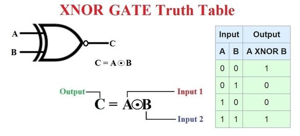
XNOR Gate
The XNOR gate is a combination inverter / NOT gate followed by an XOR gate. Its output is “true” if both inputs are “false.” Otherwise, the output is “false.”
Using combinations of logic gates, complex operations can be performed. In theory, there is no limit to the number of gates that can be arrayed together in a single device. But in practice, there is a limit to the number of gates that can be packed into a given physical space. Arrays of logic gates are found in digital integrated circuits (ICs). As IC technology advances, the required physical volume for each individual logic gate decreases and digital devices of the same or smaller size become capable of performing ever-more-complicated operations at ever-increasing speeds.
Uses of standard Logic Circuit
- Logic gates are building blocks of hardware electronic components.
- It is used in the activation of doorbells.
- The AND gates use to combine multiply signals
- The NOT gate is used in building a switch.
EVALUATION
State the uses of standard Logic Circuit
We have come to the end of this class. We do hope you enjoyed the class?
Should you have any further question, feel free to ask in the comment section below and trust us to respond as soon as possible.
In our next class, we will be talking about Computer Career Opportunities. We are very much eager to meet you there.